8 Bit Adder Circuit Diagram
[diagram] 4 bit adder circuit diagram waveform Adder bit using circuit adders half four circuits implementation watson single just box latech edu Adder fitfab circuits
8 Bit Adder Circuit - Riset
Adder bit subtractor logic fitfab wiring Adder logic wiring calculators 4 bit adder circuit diagram
Bit adder diagram using half adders schematic two electrical engineering system sum explains calculate principle
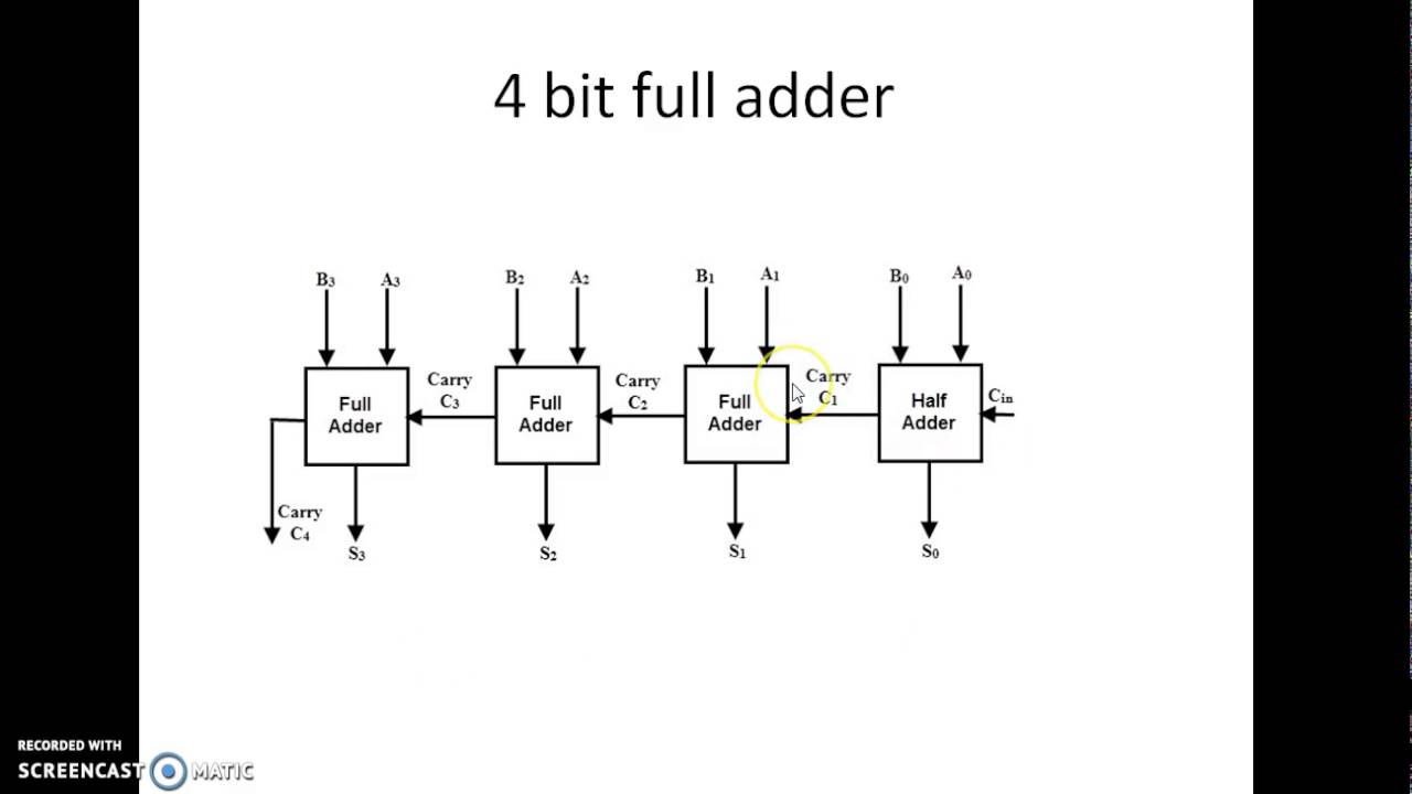
Adder logic half implementationAdder bit binary circuitverse Adder bit alu diagram block mini introduction figure finalAdder circuit construction binary circuits qiskit sourav gupta.
Adder circuitverseAdder half circuit bit make two adders logic gates electronics combined happened has Digital electronics part i : combinational circuitsBlock diagram of an 8-bit adder (32-bit adder is essentially the same.

2-bit adder: circuit's layout.
Full adder logic diagram8 bit adder circuit Logic gatesAdder subtractor ripple circuitverse.
Fitfab: 8 bit adder subtractor truth table10+ adder circuit diagram 8 bit adder subtractor circuit diagramFull adder circuit: theory, truth table & construction.
Logic gates
Copy of 3-bit binary full-adderAdder bit binary circuitverse [diagram] 8 bit adder circuit diagramCircuit diagram of a one-bit full adder using the proposed technique in.
Adder circuit circuitverseAdder parallel schematic adders advantages Adder logic binary circuit gates diagram using array inputs made twice labeled below also used4 bit adder circuit diagram.

[diagram] 8 bit adder circuit diagram
Adder combinational circuits constructed wider addersAdder bit circuit half make logic diagram comparator gates first electronics questions cout second there only solved puzzle connecting which Given a 4-bit full-adder-based alu (see diagram),Multisim adder bit binary.
Fitfab: 8 bit adder truth tableParallel adder 8 bit serial adder circuit diagram[diagram] 8 bit adder logic diagram.

Adder circuit diagram geeksforgeeks bit subtractor binary source
Adder adders libretexts circuits pageindex8-bit adder—systemmodeler model Adder bit essentiallyAdder circuitverse.
A binary adder made using and-or array logic6.4: 2-bit adder circuit .


![[DIAGRAM] 8 Bit Adder Logic Diagram - MYDIAGRAM.ONLINE](https://i2.wp.com/www.wolfram.com/system-modeler/industry/compact/examples/electrical-engineering/8-bit-adder/images/output2.png)


